Hi….folks .. welcome back..!! I am again here with another basic
electronics projects for electronics beginners , this time we are going to
discuss , how we can implement circuits for logic gates (AND, OR ,
NOT. NAND, NOR) using transistor. With the help of
these simple circuits we can easily understand the working of LOGIC GATES.
REQUIREMENTS
TRANSISTORS (BC 547)
FEW RESISTORS (220Ω)
FEW LEDs
POWER SUPPLY (5V)
CIRCUIT DIAGRAMS
AND GATE:
Here is the simple circuit diagram for implementing AND GATE
using transistors, So just implement this circuit on bread board and check the
output
SYMBOL AN TRUTH TABLE CIRCUIT
HOW TO USE
You can see there are two input terminal in AND GATE and ,
from the truth table of AND GATE you can see the output of and gate is high
only in case, when both the inputs are high, so when you will put both the
inputs high LED will glow means output is high. In rest of the cases LED does
not glow, means output is low.
OR GATE
Here is the simple circuit diagram for implementing OR GATE
using transistors, So just implement this circuit on bread board and check the
output
SYMBOL AN TRUTH TABLE CIRCUIT
HOW TO USE
You can see there are two input terminal in OR GATE and ,
from the truth table of OR GATE you can see the output is low only in case,
when both the inputs are low, so when you will put both the inputs low LED will
not glow means output is low. In rest of the cases LED glows, which means output is high.
NOT GATE
Here is the simple circuit diagram for implementing NOT GATE
using transistors, So just implement this circuit on bread board and check the
output.
SYMBOL AN TRUTH TABLE CIRCUIT
HOW TO USE
You can see there is only one input in NOT GATE. From truth
table you can see , when input is high output is low and when input is low
output is high. You can check both the conditions easily.
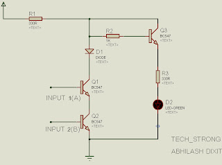
NAND GATE
Here is the simple circuit diagram for implementing NAND GATE
using transistors, So just implement this circuit on bread board and check the
output.
SYMBOL AN TRUTH TABLE CIRCUIT
NOR GATE
Here is the simple circuit diagram for implementing NOR GATE
using transistors, So just implement this circuit on bread board and check the
output.
SYMBOL AN TRUTH TABLE CIRCUIT

NOTE : for main circuit and inputs use same power supply ........:p
I hope this article was useful for you guys , in case of any
doubt, query or critical view just leave a comment.
THNX..:


No comments:
Post a Comment